POLIVOKS
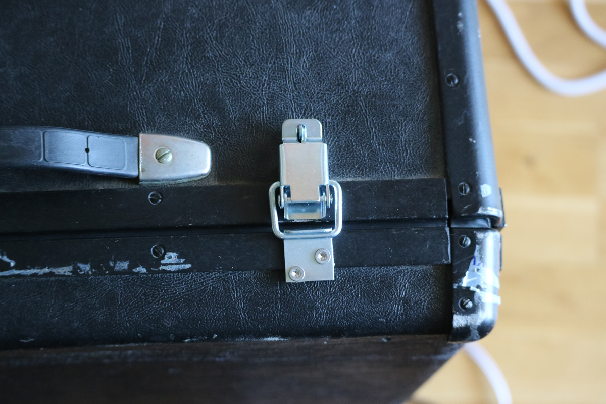
A fellow enthusiast, but much more experienced than me offered me to buy his Polivoks. Considering the fact that some tape had been wired round the case and sent to Sweden from Russia, it was in a good shape. And getting out from my volontary quarantine, driving 5-6 hours to Stockholm to pick it up was a welcome break in the daily routines.
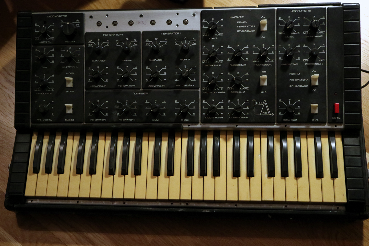
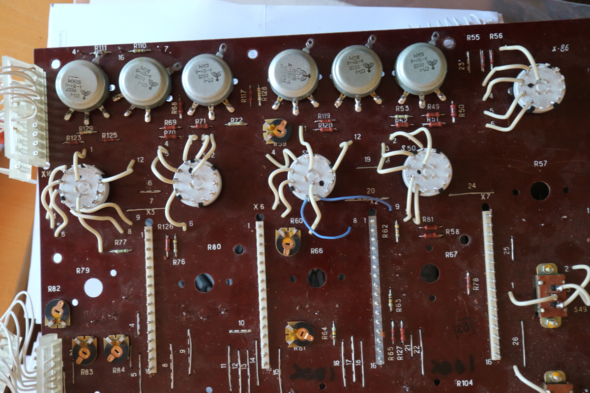
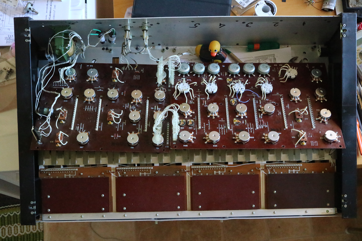
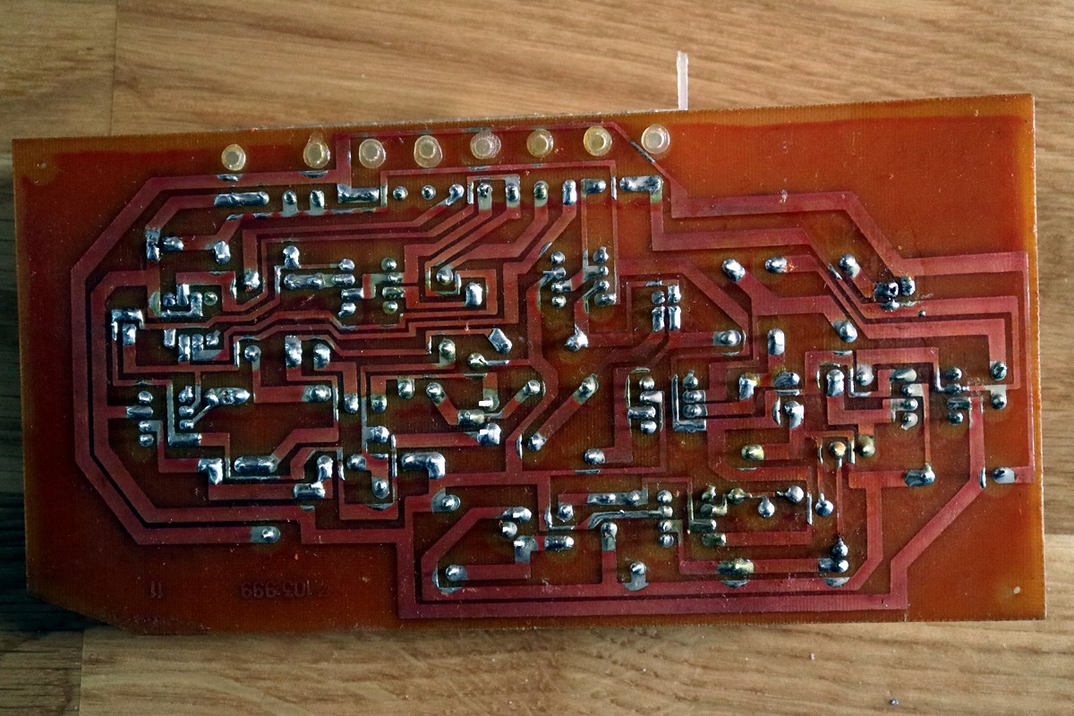
The synthesizer is made up by 3 main parts: the panel+keyboard+electronics, bottom of the case to which the synth is screwed and the cover. The main part, removed from the case looks like this.
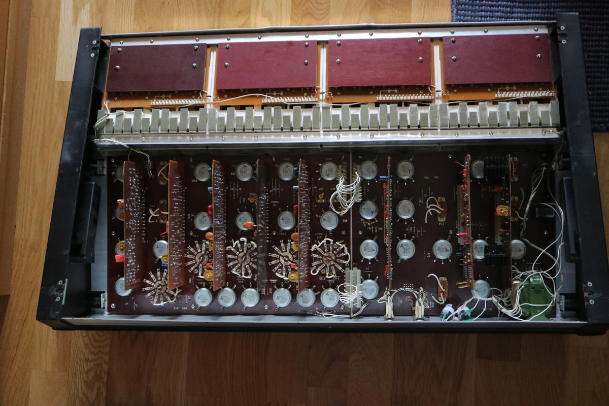
There are two main boards (motherboards) that hold all controls and eight smaller boards, each holding a separate function, like VCO, VCF, ADSR etc.
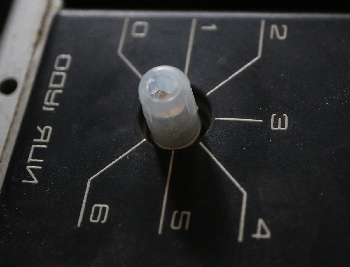
Even for this machine I wanted to do some work, namely swap the used potentiometers and rotary switches as the switches calls for a wrestler to turn (and ruins the knobs). A Russian guy on a HiFi forum was persistent that I must swap the old potentiometers.
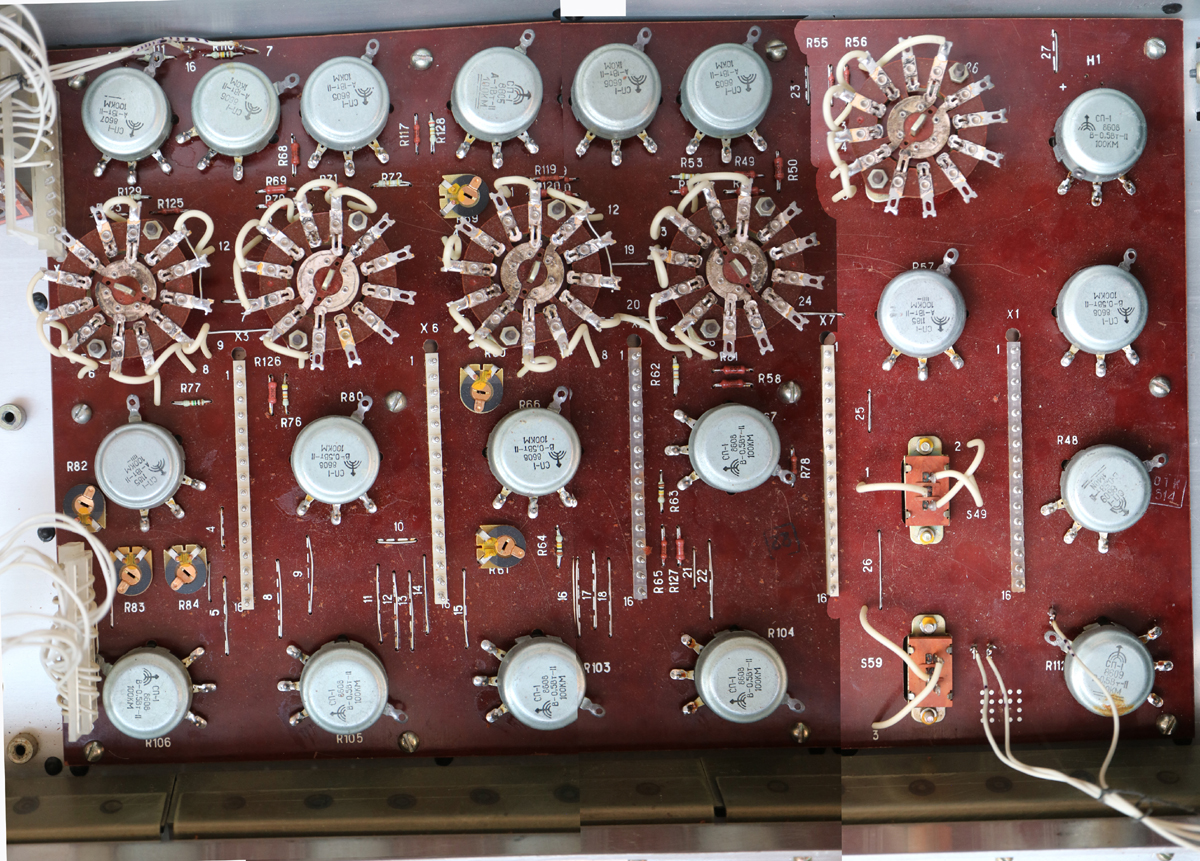
So I ordered new potentiometers and switches maken the assupmtion that A meant logarithmic and B meant linear. However in Russia it was the other way around and B, actually means V.
New switches in place.
And potentiometers ...
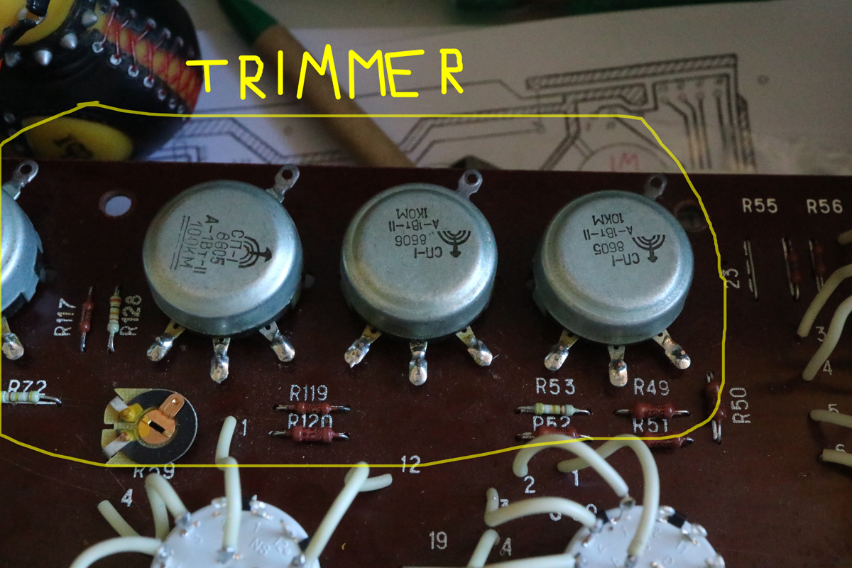
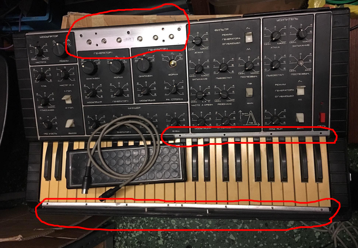
Behind a cover on the top of the panel are a number of trimmer potentiometers made up by the same type of potentiometers in the synthesizer. Haven't decided what to do, but maybe solder nice fine 10-turn trimmers to board and have them soldered and glued in place.
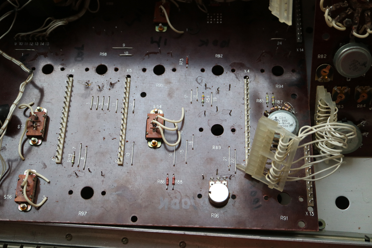
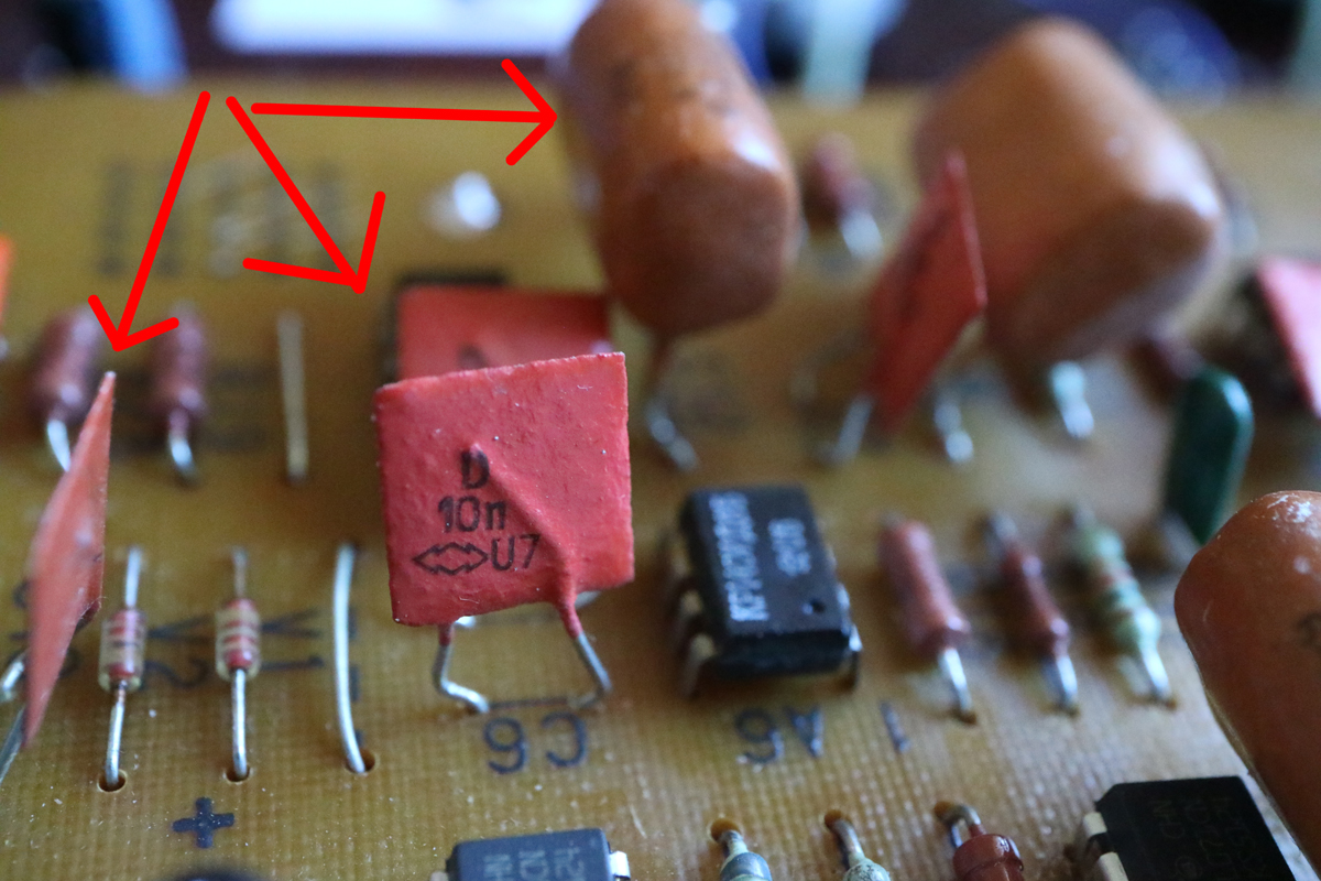
Replacing some components with bad reputation
The daughter boards have each its special funtion and are all defrent, apart from the two VCO-boards.
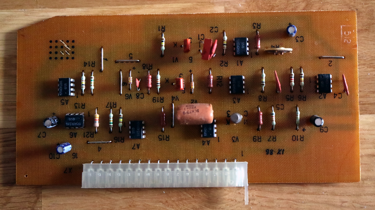
The flat and square ceramics also are on the blacklist, so new ones are ordered as well as the 220nF and 5,6nF plastic capacitors found here and there. The plastic capos may be overkill, but why not when I am still at it.
Then there's a problem with the panel. The panel covering the trimmers are missing as are some small strips here and there. Here I have a very revolutionary and maybe blasphemous idea. I know a great guy who can lasercut and laser-engrave a special kind of plastic. This material can also be bent and replace the missing details.
Special fittings to the old potentiometers and switches guaranteed these were always pointing in the right direction.
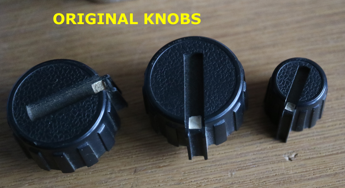
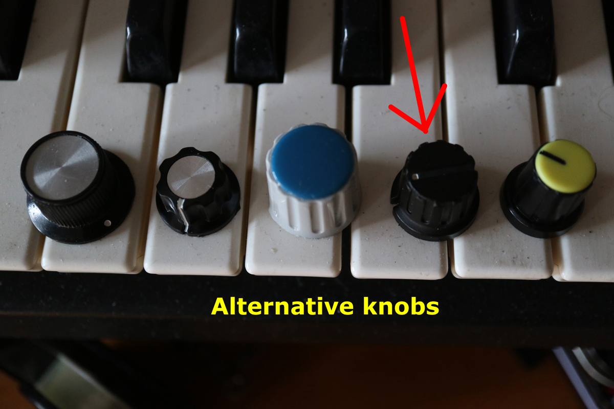
With my new controls and new knobs I can get around that issue. I have some looking like the original but I needed knobs in two diffrent dimensions, and are now ordered from Das Musikding in Germany.
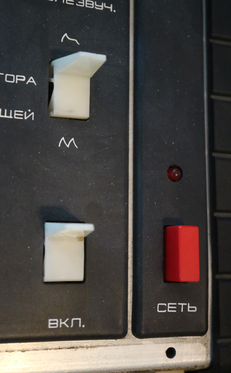
One final idea regarding the panel was the 2-way flip or paddle switches, but I will leave tham as I, so far haven't
found any to replace them.
Also the power switch doesn't get many bonus points, but I will leave it until I find something more suitable. But the red
LED is definitely in the risk of being replaced with a ..... blue one?? There's another LED showing what the LFO is up to.
So this is more or less what I intend to do with this great musical instrument. Much is done already or in the
process of being done.
What should be taken care of is to replace the DIN connectors at the back to the larger phone type. A proper IEC-conncetor
installed and maybe, maybe, maybe find a MDI-to-CV converter and have that installed as well.
Next time I visit the dentist I will ask for a whitening formula for the keys.
SCHEMATICS
LINKS